Calibrating your camera (versions 4.0-4.1)
From ARToolworks support library
Main Page > ARToolKit Professional > Calibrating your camera (versions 4.0-4.1)
Note: This page refers to an OBSOLETE method of camera calibration procedure. A new simplified procedure was introduced with ARToolKit Professional v4.3. Please see the page Calibrating your camera for the up-to-date information. This older method is still available in ARToolKit versions 4.3+, however the utility has been renamed to calib_camera-old_v3.
Contents |
Introduction
In the ARToolKit software, default camera properties are contained in the camera parameter file camera_para.dat, that is read in each time an application is started. The parameters should be sufficient for a wide range of different cameras. However using a relatively simple camera calibration technique it is possible to generate a separate parameter file for the specific cameras that are being used. In a video-see through AR interface, if the camera parameters are known then the video image can be warped to remove camera distortions. This page presents how use utility programs included with ARToolKit to calibrate your video camera.
Setting up
Calibration works by capturing an image of the pre-prepared calibration pattern with the camera, and then using the mouse to tell the software the location of the dots in the image. Getting an accurate calibration requires careful preparation of the printed image.
The calibration pattern is in the file "Calibration pattern.pdf" contained in the doc/patterns directory inside your ARToolKit Pro distribution. This PDF is designed to be printed on A4 paper. If printing on US Letter paper, you should choose to crop the PDF rather than scale it to fit the smaller paper size.
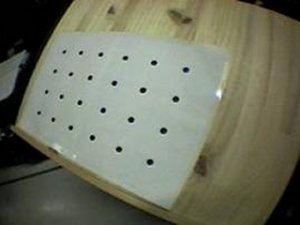
Once printed, the pattern must be affixed to a flat surface. The easiest means of doing this is to use a piece of thin flat board (as might be obtained from a hardware store) and a dry glue. Using a millimeter rule, measure the distance between the center of neighbouring dots. If printed without scaling, this distance will be exactly 40 mm. Other sizes can be used, as long as they are accurately known.
Finally, set up your camera. A calibration file is only valid for one focus setting of the camera (although it will still work at other focal lengths), so choose in advance the focus setting for the camera which will be used most often.
Running calib_camera
The "Calibration pattern.pdf" image consists of a pattern of 6 x 4 dots spaced equally apart. When viewed through the camera lens, lens distortion causes a pin cushion effect that produces uneven spacing between the dots in the camera image. The calib_camera program measures the spacing between the dots and uses this information to calculate the lens distortion.
Open a command promp (on Windows, choose "Run" from the Start menu, type "cmd", or on Mac OS X / Linux, open a Terminal window) Run the calib_camera program from the command prompt (Type calib_camera.exe on Windows, or ./calib_camera on Mac OS X / Linux) You will obtain this output in your terminal:
> ./calib_camera
Image size (x,y) = (720,486)
-----------
Mouse Button
Left : Grab image.
Right : Quit.
-----------
Calibration frames
Grabbing a frame
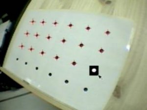
A window will appear showing live video. Point the camera at the calibration pattern so that all the dots are in view and click the left mouse button. This freezes the video image, as shown in Figure 2. If you are unhappy with the captured image, you can click the right mouse button to go back to the grabbing step.
Locating the dots
Now click and drag on the image with the left mouse button to draw a black rectangle over each dot. Start with the dot closest to the top left hand corner of the image and continue until all the dots are found. The dots must be covered in the following order:
1   2  3  4  5  6
7   8  9 10 11 12
13 14 15 16 17 18
19 20 21 22 23 24
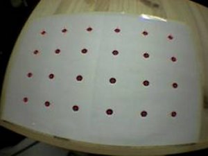
After you have dragged the mouse to make the rectangle over the dot, the image processing software will find the dot enclosed by the rectangle and place a red cross at its center. If a red cross does not appear redraw the rectangle until the dot is found. Figure 2 shows a user drawing a rectangle over one of the last dots.
While you are marking out the dots, the number of the dot will be printed in the command console, giving the following output.
-----------
Mouse Button
Left : Rubber-bounding of feature. (6 x 4)
Right : Cancel rubber-bounding & Retry grabbing.
-----------
# 1/24
# 2/24
# 3/24
# 4/24
# 5/24
# 6/24
# 7/24
# 8/24
# 9/24
# 10/24
# 11/24
# 12/24
# 13/24
# 14/24
# 15/24
# 16/24
# 17/24
# 18/24
# 19/24
# 20/24
# 21/24
# 22/24
# 23/24
# 24/24
Once all 24 dots in the image have been found click the left mouse button again. This will store the position of the dots and unfreeze the video image, ready to capture again.
----------
Mouse Button
Left : Save feature position.
Right : Discard & Retry grabbing.
-----------
  ### No.1 ###
  1, 1: 125.01, 102.84
  2, 1: 198.73, 96.19
  3, 1: 283.00, 94.30
  4, 1: 369.78, 99.93
  5, 1: 448.78, 110.33
  6, 1: 514.39, 123.37
  1, 2: 118.84, 173.96
  2, 2: 192.13, 171.33
  3, 2: 277.61, 171.27
  4, 2: 366.40, 175.28
  5, 2: 446.74, 181.88
  6, 2: 512.50, 189.64
  1, 3: 119.86, 246.72
  2, 3: 191.37, 248.83
  3, 3: 274.59, 251.42
  4, 3: 361.36, 253.61
  5, 3: 440.32, 255.61
  6, 3: 505.38, 257.05
  1, 4: 127.78, 313.80
  2, 4: 196.05, 319.71
  3, 4: 272.48, 327.11
  4, 4: 355.03, 325.72
  5, 4: 430.25, 324.01
  6, 4: 493.18, 320.03
Repeat...
You should now take another image and repeat the process for 5-10 images from various angles and positions. The more images taken the more accurate the calibration. The absolute minimum to even begin the calibration process is 2 images.
The check cycle and calculations
Once you have taken 5-10 images, click the right mouse button to stop the image capture and start calculating the camera distortion values.
-----------
Mouse Button
Left : Grab next image.
Right : Calc parameter.
-----------
[360.0, 243.0, 174.0] 596.018289
[360.0, 243.0, 174.0] 596.018289
[360.0, 243.0, 174.0] 596.018289
[360.0, 243.0, 174.0] 596.018289
[360.0, 243.0, 174.0] 596.018289
[360.0, 243.0, 174.0] 596.018289
[360.0, 243.0, 174.0] 596.018289
[330.0, 223.0, 201.0] 590.288659
[330.0, 228.0, 201.0] 486.692482
[330.0, 233.0, 201.0] 400.390511
[325.0, 238.0, 201.0] 330.137494
[325.0, 243.0, 201.0] 276.447160
[325.0, 248.0, 201.0] 241.422442
[325.0, 253.0, 201.0] 227.895132
[325.0, 253.0, 201.0] 227.895132
[325.0, 253.0, 201.0] 227.895132
[325.0, 253.0, 201.0] 227.895132
[325.0, 253.0, 201.0] 227.895132
[325.0, 253.0, 201.0] 227.895132
[325.0, 253.0, 201.0] 227.895132
[325.0, 253.0, 201.0] 227.895132
[325.0, 253.0, 201.0] 227.895132
[325.0, 253.0, 201.0] 227.895132
[325.0, 253.0, 201.0] 227.895132
[325.0, 253.0, 201.0] 227.895132
[324.0, 253.5, 201.0] 227.334239
--------------
Center X: 324.000000
Y: 253.500000
Dist Factor: 201.000000
--------------
-----------
Mouse Button
Left : Check fittness.
Right :
1/10.
-----------
It will take a while to calculate these parameters, please be patient. The center x and y values and distortion factor are the final key values generated by the first calculation cycle. These values will be different for every camera.
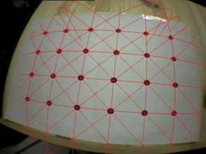
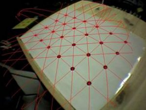
At the end of this cycle, the program will prompt you to view the calculated parameters against the capture images. In order to check that these parameters are correct click the left mouse button again. This will show the first image grabbed with red lines drawn through the calibration dots. These lines should pass through the center of each of these dots (see Figure 4). Each time the left mouse is clicked the next grabbed image will be shown.
Following the image verification, the program will run through a second calibration cycle, to calculate the camera parameter. This can take many minutes, so be patient.
Saving the calibration file
At the end of the calibration calculation cycle, you will be prompted for a file name to store the parameters in:
point_num = 315
--------------------------------------
SIZE = 720, 486
Distortion factor = 324.000000 253.000000 201.000000
372.97979 -24.50134 248.86941 0.00000
0.00000 327.03507 122.42421 0.00000
0.00000 0.00000 1.00000 0.00000
--------------------------------------
Input filename: camera_para-MYCAMERA.dat
Once the values are stored in a camera data file hit the right mouse button to quit. You will find the camera parameter file in the current working directory, usually the same directory as the calib_camera program, or also possibly in your home directory (e.g. on Mac OS X).
Using the calibration file
By changing the name of this camera data file to camera_para.dat and placing it in the bin/Data directory it can be used immediately in the ARToolKit sample programs. Calibrating your camera should give improved tracking results.
Stereo camera calibration
If calibrating a stereo camera, calibrate each eye separtely first, saving the parameters, then run the program calib_stereo to perform the final step of inter-occular calibration.