An Introduction to OpenSceneGraph and osgART
From ARToolworks support library
Main Page > osgART > An Introduction to OpenSceneGraph and osgART
Contents |
Introduction
This chapter provides a conceptual introduction to developing 3D applications using OpenSceneGraph, and extension of OSG development to augemented reality (AR) applications with the addition of marker tracking provided by ARToolKit.
OpenSceneGraphhttp://www.openscenegraph.org/
ARToolKit
http://www.hitl.washington.edu/artoolkit/
http://artoolkit.sourceforge.net/
http://www.artoolworks.com/products/artoolkit/
OpenSceneGraph
OpenSceneGraph (OSG) is essentially a higher-level abstraction for OpenGL. OpenGL is a low level API for developing computer graphics applications. OSG sits on top of OpenGL, allowing the programmer to combine many small OpenGL operations into one logical group. A collection of related logical groups which together make up a scene is called a scene graph. OSG is an open-source scene graph implementation, hence the name.
OSG provides many additional features to make 3D application development easier.
- Loaders for a number of 3D graphics formats and image formats.
- Cross-platform compatibility.
- A plug-in architecture which allows non-OpenGL structures to be referenced in the scene graph, e.g. positional audio sources.
http://www.opengl.org/
Scene Graphs
A scene graph is simply an arrangement of nodes that represent the 3D scene hierarchically. It is a tree structure with a root, internal nodes and leaves. Typically, the internal nodes represent transformations and rendering states, and the leaves represent geometry.
A rendering of the scene is produced by traversing the tree in a depth-first manner, and drawing the leaves (geometry) with all the transformations and state changes introduced by their ancestors. Developing with a scene graph is quite different from developing directly with OpenGL. A scene graph is built and maintained throughout the lifetime of the program whereas a standard OpenGL applications constructs everything from scratch each frame. Of course, this is exactly what a scene graph like OSG is doing behind the scenes, but this is hidden from the developer.
Beyond adding a convenient structure to a 3D application a scene graph can also aid performance. Because updates to the scene graph and rendering can occur at different times, the scene graph can perform many optimisations at render-time. For example, entire branches of the scene graph can be ignored during rendering if the scene graph can realise that none of the branch will actually be visible.
A Simple Scene Graph
The diagram to the left is a visual representation of a simple scene graph. The root node only has one child, a translation node, which itself has one child, some geometry.
When this scene graph is drawn, the renderer will traverse the graph. In this case this will simply involve stepping down the single branch.
The renderer will begin in a default state. That is, with the view set to the identity. When it encounters the translation node, the current modelview matrix will be updated to accommodate a translation of 10, 10, 10. The cube geometry will then be drawn.
Here we provide the OSG source code that would be used to create the scene graph shown above. This code could be considered a minimal OSG example, to which we will later add.
#include <osg/MatrixTransform>
#include <osg/Geode>
#include <osg/ShapeDrawable>
#include <osgProducer/Viewer>

int main( int argc, char **argv )
{
    // Set up a window for OSG drawing.
    osg::ArgumentParser arguments(&argc,argv);
    osgProducer::Viewer viewer(arguments);
    viewer.setUpViewer(osgProducer::Viewer::STANDARD_SETTINGS);

    // Create a geode node containing one drawable, a blue cube.
    float boxSize = 1.0f;
    osg::ShapeDrawable* sd = new osg::ShapeDrawable(new osg::Box(osg::Vec3(0, 0, boxSize / 2.0f), boxSize));
    sd->setColor(osg::Vec4(0, 0, 1, 1));
    osg::Geode* _cube = new osg::Geode();
    _cube->addDrawable(sd);

    // Set up a transformation node to position the cube, and init the scene graph with it.
    osg::MatrixTransform* _trans = new osg::MatrixTransform;
    _trans->addChild(_cube);
    _trans->setMatrix(osg::Matrixd::translate(10,10,10));

    viewer.setSceneData( _cube );

    // Put everything together, and let the viewer take over.
    viewer.realize();
    while( !viewer.done() )
    {
        // The main loop.
        viewer.sync(); // wait for all cull and draw threads to complete.
        viewer.update();
        viewer.frame();
    }

    // The viewer has exited. Do some cleanup and exit.
    viewer.sync();
    viewer.cleanup_frame();
    viewer.sync();
    return 0;
}
Introducing AR
Simply expressed, Augmented Reality (AR) is the term used to describe interfaces that embed 3D computer graphics into the "real" world. Research into AR has been going on for many years in a variety of fields including engineering, education, entertainment, military and medical.
Video see-through AR
Video See-Through AR is one approach to creating an AR interface. Other approaches include Optical See-Through and Hand-Held AR.
Video See-Through AR involves compositing a live video feed with 3D graphics. Typically such an interface requires the user to wear a head-mounted display (HMD). A small camera is placed on the HMD in approximately the position of the user’s eyes. This gives the impression that the user is seeing the world from their own perspective, adding to the illusion of an augmented reality.
The computer analyses each frame from the camera to determine where and how to draw the 3D content. This process is called registration.
ARToolKit
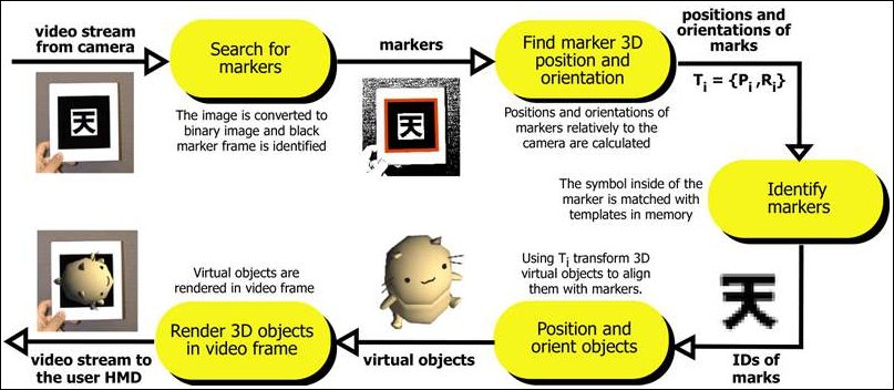
The ARToolKit is a software library that performs the tasks of video capture, image registration, and image overlay for video see-through AR applications. The basic ARToolKit recognises special black and white markers in the camera frames and can calculate their positions and orientations. With this information, 3D graphics can be drawn so that they appear connected to the markers.
ARToolKit Professional documentaion
[1] ARToolKit v2.x documentation
osgART
We can use OSG to do the 3D rendering for us, and ARToolKit to do the registration for us. osgART is a library that allows these two libraries to work together.
osgART provides a collection of classes that make it easy to make AR applications in OSG. There are three main components to consider:
- Video background
- Projection matrix
- Transformations
The video background is the live video-feed from the camera. This needs to be drawn behind all other 3D geometry to maintain the illusion that the 3D objects are in fact embedded in the real world.
The projection matrix used by ARToolKit needs to be applied within OSG. The projection matrix is generated from the intrinsic parameters of the camera being used. These are collected in a calibration process.
The transformations of markers, computed by ARToolKit, need to be mapped to OSG transformations. This allows models to be drawn in OSG so that they stay "attached" to the markers.
osgART concepts
One way of positioning an object in a scene graph is to place it beneath a transformation node. Your program can then change the values of the transformation to set the objects position, rotation and scale. This is exactly what osgART does. osgART updates transformations in the scene graph to match the transformations computed by ARToolKit. If you place an object beneath one of osgART's transformation nodes, the object will move with the marker.
- The ARToolKit provides transformation matrices for each marker it recognises in the camera frame.
- OSG uses transformation nodes to position 3D geometry within the scene.
- osgART maps ARToolKit transformations onto OSG transformation nodes.
In addition to managing transformations, osgART also handles the drawing of the video frame itself. The frame data (a buffer of bytes) is transferred into a texture each frame. The texture is drawn behind all 3D content.
The ARToolKit can also remove camera distortion from frames. osgART supports this feature as well. It can be enabled when the video background is created.
Transferring this data to the graphics card is a potential bottleneck. Various optimisations made available by OSG can be used, such as the OpenGL TextureRectangle extension. This can be enabled in osgART when the video background is created.
From here, it is recommended to proceed to osgART tutorial 1: First simple osgART scene.